This is a modified version wolkstein/MavLink_FrSkySPort with OpenTX2.1 and APM 3.3 / Hardware are using ATmega32U4 https://github.com/wolkstein/MavLink_FrSkySPort
This is a modified version of the mavlink to frsky s.port code found here: http://diydrones.com/forum/topics/amp-to-frsky-x8r-sport-converter
It's based on the official 1.3 version.
Teensy Compile INFO: uncomment line 79 in MavLink_FrSkySPort.ino to enable processing of MavLink Message RC_CHANNELS, currently not in use, but can be used for extending possibilities of e.g. controlling LEDs or other addons.
comment line 92 & 93 in MavLink_FrSkySPort.ino to disable the "Single Cell Lipo Voltage Monitor" functionality to use reported Mavlink voltage instead.
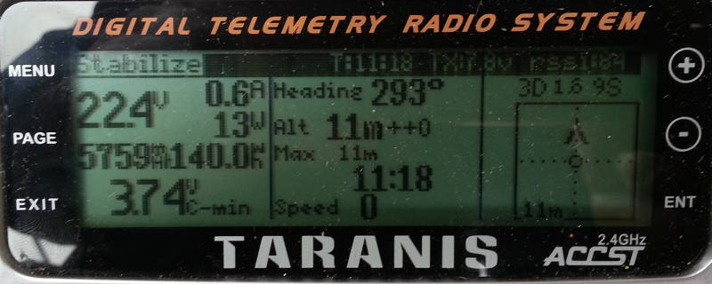
The main focus of this script and teensy modification is the exact monitoring of the flight battery capacity and voltage. The consumption in mA / h and watt-hours can be calibrated on a separate model script. Moreover, by the modification described below on teensy, which are allowed lipo monitors individual cell voltage. The radar on the left represents the position and the orientation of the vehicle.
The interface between the APM/PixHawk and the FrSky X series receiver is a small Teensy 3.1 board running a custom protocol translator from Mavlink to SPort telemetry.
Almost all the parameters on the normal telemetry screens of the Taranis X9D are correct, with some exceptions (RPM and T2), that combine multiple values on a single field.
Cell ( Voltage of Cell=Cells/(Number of cells). [V])
Cells ( Voltage from LiPo [V] )
A2 ( HDOP value * 25 - 8 bit resolution)
A3 ( Roll angle from -Pi to +Pi radians, converted to a value between 0 and 1024)
A4 ( Pitch angle from -Pi/2 to +Pi/2 radians, converted to a value between 0 and 1024)
Alt ( Altitude from baro. [m] )
GAlt ( Altitude from GPS [m])
HDG ( Compass heading [deg]) v
Rpm ( Throttle when ARMED [%] *100 + % battery remaining as reported by Mavlink)
VSpd ( Vertical speed [m/s] )
Speed ( Ground speed from GPS, [km/h] )
T1 ( GPS status = ap_sat_visible*10) + ap_fixtype )
T2 ( Armed Status and Mavlink Messages :- 16 bit value: bit 1: armed - bit 2-5: severity +1 (0 means no message - bit 6-15: number representing a specific text)
Vfas ( same as Cells )
Longitud ( Longitud )
Latitud ( Latitud )
Dist ( Will be calculated by FrSky Taranis as the distance from first received lat/long = Home Position )
Fuel ( Current Flight Mode reported by Mavlink )
AccX ( X Axis average vibration m/s?)
AccY ( Y Axis average vibration m/s?)
AccZ ( Z Axis average vibration m/s?)
Also, this script relies heavily on voice alerts and prompts.
The screen explanation:
A-Current Flight Mode Active as reported by the Flight Controller. If blinking the vehicle is not Armed.
B-Wh Gauge. Display Battery capacity left. Need an Setup Value in Mixes/offset.lua which holds your real battery capacity in Wh.
C-Radio Transmitter Battery Voltage.
D-RSSI value
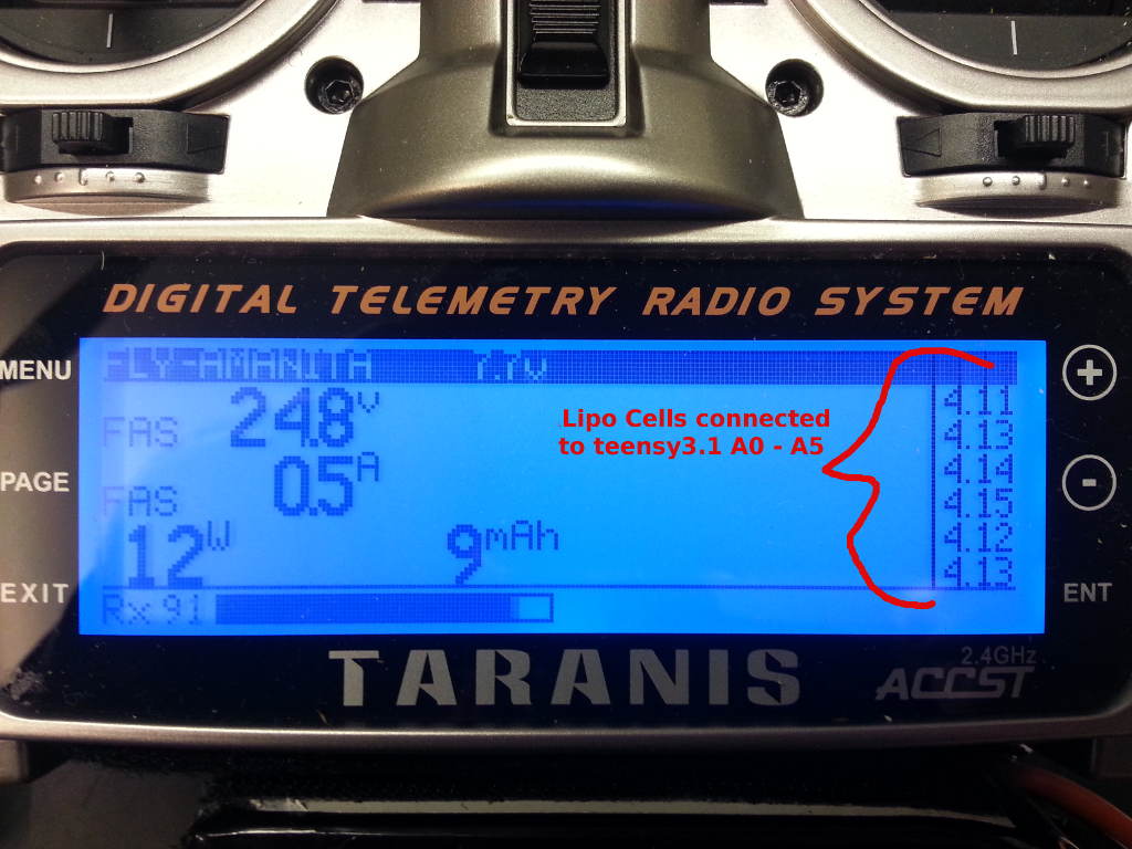
E-Reported Flight Battery Voltage from MavLink or if teensy a0-a6 are connected will measured Voltage from lipo balancer connectors.
F-Reported Flight Battery Current.
G-Actual power output in Watts (VxA)
H-consumed power in mAh, offset adjustable from Modelscript
I-consumed power in Wh, offset adjustable from Modelscript
J-Lipo Cell minimum. this simple display lowest cell from your lipo
K-Heading in degrees
L-Baro-Altitude
M-Maximum reached Altitude
N-Armed Time Timer - Starts and stops when the Vehicle is armed/disarmed
O-Speed in Km/h
P-GPS Indicator, 3D, 2D or no status
Q-HDop indicator. Blinks when over 2
R-Number of reported satellites
V-Radar
S-Vehicle Arrow can move and rotate. this display position relative to home and heading relative to home
T-Home/Centre Position
U-Distance to home (Distance to the point the Taranis received a good satellite fix)
W-Vertical Speed in meters per minute
the script is optional to use. It's enable audio messages to status of lowest lipo cell. this script allows you to setup your cell audio info-messages, warning-messages and alarm-messages.
- Crit,V/100, setup Critical Voltage alarm level. The value is divided by 100. 320 mean 3.2V
- Use Horn, 0 = no horn, 1 = sine horn, 2 = other sine horn, 3 = another sine horn
- Warn,V/100, setup Warn Voltage level. The value is divided by 100. 320 mean 3.2V
- Rep,Sec,setup time in S between repeating warn and critical voltage level is reached.
- Drop,mV, if you are not lower than warn level voltage messages will repeated dependent to voltage drop on lowest cell. 100 mean each 0.1 Volts cell drop an Audio Voltage info play the Cell Voltage with PREC 2.
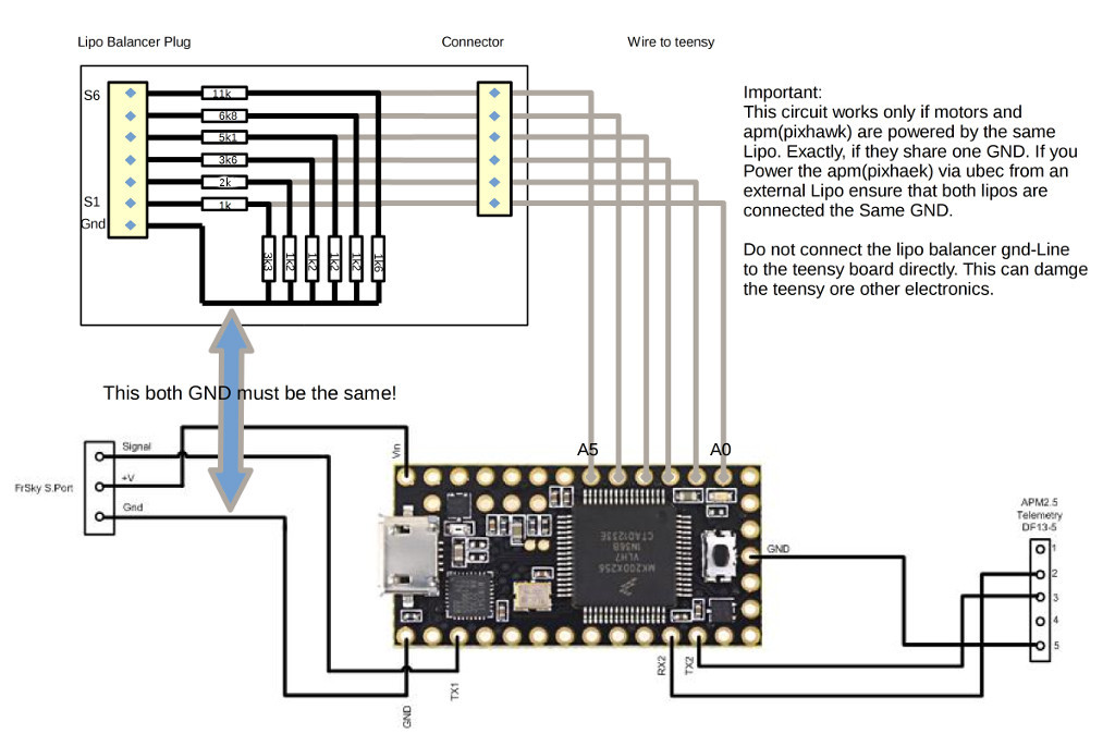
this increase the teensy functionality to measure all lipo cells separate via lipo balancer jack. this require teensy pins A0 to A5(6S Lipo) connected via an voltage divider resistor network.
if connecting the lipo balancer plug to your teensy, it will be important to divide all lipo-cell voltage outputs to a value <= 3,3V.
example for an full 6S Lipo(25,2V):
LipoCell | R1 in series to cell | R2 to gnd | software divider
S1 4,2V | 1k | 3k3 | 237.350026082
S2 8,4V | 2k | 1k2 | 116.006256517
S3 12,6V | 3k6 | 1k2 | 77.3509473318
S4 16,8V | 5k1 | 1k2 | 58.7966886122
S5 21,0V | 6k8 | 1k2 | 46.3358699051
S6 25,2V | 11k | 1k6 | 39.4176445024
all needed resistors found in E24 series. the divider are defined in MavLink_FrSkySPort.ino. if you use other resistors all dividers must recalculated.
Properly discharged. It is important in principle not to overload the battery! What can be seen but the overload of a LiPo battery?
On the following four points overloading can be easily found:
- Under load, voltage dips resulting from less than 3.3V per cell.
- The capacity of the battery is fully utilized. Use of more than 80% of the nominal capacity is not meaningful.
- The idle cell voltage (no load on LiPo), should never lie or fall below 3.6V.
- The LiPo battery is extremely hot after discharge. The LiPo may be warmer than 60 ° C are under any circumstances. the damages sustained chemistry!
If we can we monitor multiple readings of the battery during the flight very accurately judge the battery status and so exploit the maximum flight time with a maximum protection of the battery.
How can we help here telemetry screen No.1?
- First, In flight (ie under load), the cell voltage should never fall below 3.3V. This helps us Lable "J" lipo cell voltage Minimal. It is helpful audio prompts for the cell voltage adjust so the sounds of the Critical alarm at 3.3V. In this setting, we always get to hear the alarm if we for example. overload the lipo at full throttle passages. In this case, of course, the flight stick adapt. Should this happen in the first few minutes of flight, their system might be set incorrectly or her lipo is unterdimensoniert or too old.
- Second, monitor the power output of the battery. Label H = mAh and I = Wh help us here. All batteries have a specified amount of energy in Wh. And the capacity is measured in mAh. We should have a Lipo, DO NOT drain more than 80% in order to keep the number of cycles of Lipo high. That is for us if we we were to fly, for example with a 8000 mAh battery deprive him only 6400mAh capacity. Or if we stick to the amount of energy in Wh, we should consume only 70,4Wh with a printed on the battery indication of 88Wh.
- thirdly, the open circuit voltage of the battery should not under 3.6V traps. You can verify this by reading the value of the Cellen Minumum voltage (lable "J") after the flight. (System Disarmed status).
- fourth, Lipo to hot >60°. if this happens something goes wrong!! check system and calculation of components
Simple percentage calculation in battery capacity
example:
80% of 8000mAh battery with 88Wh capacity.
8000mAh ÷ 100% × 80% = 6400mAh
or
88Wh ÷ 100% × 80% = 70,4Wh
Telemetry screen battery calibration with the help of a lipo charger. Most chargers inform us about the amount of energy in Wh and mAh which flows during charging in the battery. If we now compare the values of the charger (reference) with the values of the telemetry screen it should be possible to make a fairly accurate comparison. In our case, we take the model scripts offset.lua to help.
We can set from the linear function (Wh = P x t and Ah = V x I xt) dependent Percentage offset for mAh and Wh here. "BatCap Wh" is needed by Wh consumption Gauge. This simply hold the Real Battery capacity in Wh. This is needed to display the Wh Gauge consumption correctly.
-
First, we fly a few empty batteries and keep a record of the displayed telemetry values for mAh and Wh. Of course, we arrange the batteries and values so we do not get confused later. (1 = Battery 5055mAh and 120,3Wh, Battery 2 = ... ..., battery 3 ...).
-
secondly, we load the empty flown batteries and keep a record of the relevant energy quantity from the charger. naturally sorted so that we can still assign the measured values of the Relevant flight.
-
Thirdly, we make our Percentage offset calculation. A very simple calculation.
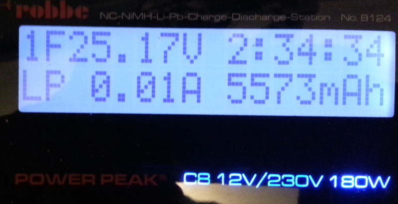
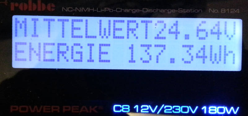
Example of battery 1: we had on our charger a display of example. 5573mAh and 137,34Wh. The telemetry screen had but here 5055mAh and 120,3Wh displayed.
then we calculate:
Charger ÷ telemetry screen
5573mAh ÷ 5055mAh = 1.10247
The decimal places of the result give the Percentage offset. the means for our mAh offset is rounded 10%
the same calculation for Wh
137,34Wh ÷ 120,3Wh = 1,14164
the means for our Wh offset is rounded 14%
when we perform these calculations for all batteries, we can use later an average.
At the very end we make it up a flight test and compare the new values of the telemetry again with the values of the charger to recharge the batteries. Now should the values of the telemetry prefer a little higher than the be the charger. 1-5%. Higher values on the telemetry display of course prevent a negative charging of the batteries.


